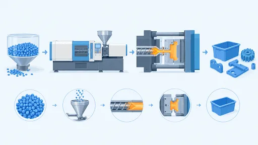

Plastic part design sets the wall thickness, draft, radii, ribs, and material before any mold is machined. These choices decide how the plastic fills the mold, how it cools and how the finished part releases. Applying DFM guidelines at the drawing stage keeps a design moldable from the first mold. Each guideline links a design feature to a measurable result on the finished part, such as flatness, dimensions, or surface appearance.
What Is Plastic Part Design for Injection Molding?
Plastic part design for injection molding is the work of shaping a part so that molten plastic fills the mold, cools evenly and releases in its intended shape. Design for manufacturability (DFM) reviews each feature of the design against how the mold and machine operate, and injection mold design then turns the approved part into a mold. Injection molding design guidelines turn that review into repeatable rules for walls, draft, radii, ribs, and bosses.
Design decisions follow a fixed order. Each one limits the choices available to the next:
- Resin grade, the specific plastic material chosen, which sets shrinkage and the recommended wall range.
- Nominal wall thickness, the thickness that the main body of the part uses.
- Draft angle and corner radius on every face and edge.
- Rib and boss design for stiffness and fastening.
- Gate location, the point where plastic enters the mold.
How Should Wall Thickness Be Set?
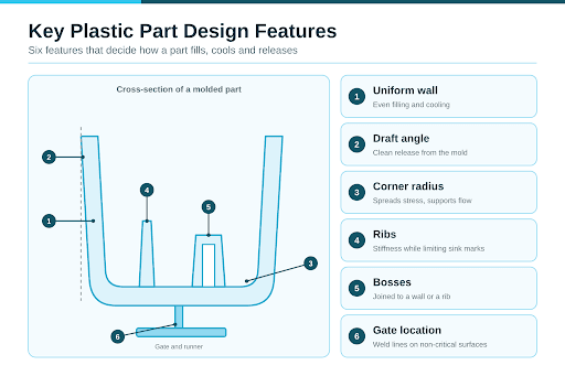
Wall thickness in injection molding starts with the nominal wall. In plastic injection molding, a uniform nominal wall lets the plastic fill and cool at the same rate across the part, which supports flat surfaces and consistent dimensions. Resin suppliers publish the wall range that each material fills reliably, so the resin is chosen before the wall is drawn.
- Join thick and thin areas with a tapered transition.
- Core out thick sections, which means removing material from the inside, so that the wall stays uniform.
- Keep ribs, bosses, and corners in proportion to the wall they join.
Why Do Draft Angle and Corner Radius Matter?
Draft angle is the slight taper on faces that run parallel to the direction the mold opens. A draft of at least 1 degree lets the part slide out of the mold cleanly, and textured faces take added draft because the texture grips the mold surface.
Corner radius is the rounding applied to an edge or a corner. Research on corners in injection molding links uneven cooling at corners to part warpage. A rounded corner lets the plastic flow around it and spreads stress, and an inside radius of at least half the wall thickness is a common starting guideline.
- Apply draft to every face parallel to the mold opening direction, including ribs and bosses.
- Add draft on textured faces according to the texture depth.
- Round inside corners, and give the outside corner a radius equal to the inside radius plus the wall thickness to maintain a constant wall.
How Are Ribs and Bosses Designed?
Ribs are thin walls that stiffen a part and keep its weight down. Rib and boss design depends on proportion, and a rib thickness of 40 to 60 percent of the wall it joins limits sink marks, the surface dents that form above a thick section. A boss is a cylindrical post that holds a screw or a pin, and it carries load through its connection to the wall.
- Add a radius at the base of each rib to spread stress.
- Taper ribs with draft so they release from the mold.
- Join each boss to a nearby wall with a rib so that it carries load.
- Keep boss walls thin so that the surface above stays flat.
Which Plastic Part Design Rules Apply to Each Feature?
Plastic part design guidelines pair each feature with a rule and the reason behind it. These starting values suit general-purpose resins, and the resin supplier's data sets the final figure.
| Feature | Guideline | Reason |
|---|---|---|
| Nominal wall | Uniform, within the resin supplier's range | Even filling and cooling |
| Wall transition | Gradual taper | Limits stress at the change |
| Draft angle | At least 1 degree, with added draft on textured faces | Clean release from the mold |
| Inside corner radius | At least 0.5 times the wall thickness | Spreads stress, supports flow |
| Rib thickness | 40 to 60 percent of the joining wall | Limits sink marks |
| Boss wall | Thin, joined to a wall or rib | Keeps the surface flat |
| Thick section | Cored out | Maintains a uniform wall |
How Do Material and Gate Location Shape Plastic Part Design?
Resin choice sets how much the part shrinks as it cools, so the mold cavity, the hollow space that forms the part, is machined during injection mold manufacturing to the finished part size plus a shrinkage allowance. Glass-filled and unfilled grades of the same resin have their own shrinkage values, which affect flatness and hole positions.
Gate location decides where two streams of plastic meet and where weld lines, the visible seams at the meeting point, form. Mold flow analysis, a simulation of how plastic fills the cavity, shows weld lines and trapped air on the part model before tooling begins.
- Position the gate so that weld lines fall on non-critical surfaces.
- Run mold flow analysis on the part model to confirm the fill pattern.
- State the shrinkage allowance for the chosen resin grade on the drawing.
What Should Be Checked Before Tooling Starts?
A review before tooling confirms each design decision while the part is still a drawing. Working in a fixed order covers each decision once.
- Confirm the resin grade and its shrinkage allowance.
- Check the nominal wall and every thickness transition.
- Confirm draft on ribs, bosses, and every wall face.
- Review corner radii, rib proportions, and boss connections.
- Identify undercuts, the features that block release and may need side actions, which are moving mold sections that form them.
- Review gate location against the mold flow analysis results.
How Does Radiant Design Support Plastic Part Design?
An injection mold manufacturing company in India applies plastic part design rules in the DFM and mold design service, where wall thickness, draft, radii and gate location are reviewed before the mold is machined. Injection mold manufacturing then builds the mold to the approved design, and injection molding and production run the approved part.